Edit Jan 30, 2018: fix udev permissions commands. updated firmware commands
In my previous posts of this series, I’ve gone from nothing to programming the stm32f103c8t6 to blink and interact with a terminal window. I’ve covered:
- First post:
- generation of boilerplate code with STMCubeMX
- compilation with gcc for ARM
- controlling digital output,
- Second post:
- sending and receiving UART communications both with blocking/polling methods as well as interrupt based
- the non-obvious software installation steps needed to get it all to work.
All of the code can be found on github.
In this post
I cover two things
- sending data over SPI. This is the easy part; if you understood my other two posts, you don’t really need help with this
- receiving the sent signals with a cheap logic analyzer and the open source PulseView/Sigrok software. Being able to monitor digital signals is a handy, probably critical, tool to have.
Needed hardware
Beyond the stm32 module and stlink programmer, you’ll need a cheap 8 channel logic analyzer module from ebay/AliExpress. “usb 8ch logic” is a good set of search terms. Price is <$5 delivered.
Boilerplate code
For this project, I begin with the basic_uart STMCubeMX configuration. Only a few changes are needed:
- In the pinout tab, I go to SPI1 and change the mode to “full-duplex master”
- Under configuration tab -> SPI1 -> parameters, I change “prescaler” to 64, yielding a 1Mb/s data rate. Fast, but not too fast. Seems like a bunch of devices out there max at ~10Mb/s
- Under configuration tab -> SPI1 ->NVIC, I activate “SPI1 global interrupt”
Sending SPI data
Referencing the HAL documentation once again, section 37.2.3. The code needed to send a message is easy1
[code]
HAL_SPI_StateTypeDef spistate = HAL_SPI_GetState (&hspi1);
if (spistate == HAL_SPI_STATE_READY) {
HAL_StatusTypeDef hstatus __attribute__ ((unused));
if (spi_poll) {
hstatus = HAL_SPI_Transmit(&hspi1, spimessage, sizeof(spimessage), HAL_MAX_DELAY);
} else {
hstatus = HAL_SPI_Transmit_IT(&hspi1, spimessage, sizeof(spimessage));
}
spi_poll = !spi_poll;
spistate = HAL_SPI_GetState (&hspi1);
}
[/code]
Now we’re done right? This wouldn’t be an interesting post if I left it there.
Monitoring SPI output with a logic analyzer
Given the code above, how can we verify that the data is actually being sent? My answer to this is to use a cheap logic analyzer module together with PulseView/Sigrok. I have some tips/comments on installing it below, but let’s first see what it can do.
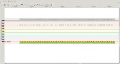
It shows that the values: 0x54, 0x68, 0x69, 0x73, 0x20… was received. There are people out there who can read ascii in hex format. I am not one of those people. Consulting an ASCII table, the values above correspond to: “this “. I wasn’t able to find a way to get Pulsview to translate these for me in the GUI, but there’s another, perhaps better, way. Sigrok-cli.
sigrok-cli
Pulseview is just a GUI for the sigrok interface/library. Sigrok talks to the capture device and it does the protocol decoding. Probably most interesting, you can save, process, munge,… the captured data from the output.2
Let’s first see that sigrok-cli can see the logic capture module. The second one listed is the one of interest.
[code]
–> sigrok-cli –scan
The following devices were found:
demo – Demo device with 12 channels: D0 D1 D2 D3 D4 D5 D6 D7 A0 A1 A2 A3
fx2lafw:conn=1.31 – Saleae Logic with 8 channels: D0 D1 D2 D3 D4 D5 D6 D7
[/code]
Let’s grab a handful of samples3
[code]
–> sigrok-cli –driver=fx2lafw –config samplerate=8M –samples 10
libsigrok 0.6.0-git-bb0c527
Acquisition with 8/8 channels at 8 MHz
D0:00000000 00
D1:11111111 11
D2:00000000 00
D3:11111111 11
D4:11111111 11
D5:11111111 11
D6:11111111 11
D7:11111111 11
[/code]
We asked for 10 samples, so we got 10, from left to right.
I’ll skip a couple steps of explanation, which I’ll come back to, but if you do this:
[code]
sigrok-cli –driver=fx2lafw –config samplerate=4M –continuous -P spi:clk=D2:mosi=D1:wordsize=8 –protocol-decoder-annotations spi=mosi-data | perl -ne ‘my ($a, $b) = split(/ /, $_); print $a, " – ", chr(hex($b)), "\n"’
[/code]
you can get this:
[code]
–> sigrok-cli –driver=fx2lafw –config samplerate=4M –continuous -P spi:clk=D0:mosi=D2:wordsize=8 –protocol-decoder-annotations spi=mosi-data | perl -ne ‘my ($a, $b) = split(/ /, $_); print $a, " – ", chr(hex($b)), "\n"’
spi-1: – T
spi-1: – h
spi-1: – i
spi-1: – s
spi-1: –
spi-1: – t
spi-1: – i
spi-1: – m
spi-1: – e
spi-1: –
spi-1: – t
spi-1: – h
spi-1: – e
spi-1: –
spi-1: – s
spi-1: – p
spi-1: – i
spi-1: –
[/code]
Installation notes
Now that I’ve shown some simple, yet powerful, things that can be done, let’s look at how to install the needed software and further down, I’ll describe how I learned to use the cmdline options I used.
This section of this blog post is not intended to be a complete howto, but rather additions to the instructions on the sigrok site. They are based on my experience with an Ubuntu 16.04 system.
I recommend compiling sigrok/pulseview; “apt install” gave me an older version that didn’t work as well for me. The online instructions are pretty good and the process is not that hard. Here are my additions:
I found some of the qt5 components are missing. I fixed this by doing this:
[code]
sudo apt install qt*5-dev
[/code]
This is a shotgun approach. For what may be a better answer, I recommend reading this stackover flow answer.
Once I did this, the instructions work well. I’ve attached the command list that I used (according to my, perhaps incomplete notes) to the end of this section. Maybe they will save some time relative to cutting/pasting from the build instructions
Device permissions
Like most usb devices, you need to have read/write permission to use them. Let’s find the device 4
[code]
lsusb | grep -i sal
Bus 001 Device 031: ID 0925:3881 Lakeview Research Saleae Logic
[/code]
Without permission, you’ll get an error like this:
[code]
sigrok-cli –scan
sr: fx2lafw: Failed to open potential device with VID:PID 0925:3881: LIBUSB_ERROR_ACCESS.
[/code]
To gain permission, you’ll want to copy the udev file include in the libsigrok code:
[code]
sudo cp ./libsigrok/contrib/*.rules /etc/udev/rules.d/
[/code]
Device firmware
When you try running for the first time, you’ll likely get an error like this one:
[code]
–> sigrok-cli –scan
sr: resource: Failed to open resource ‘fx2lafw-saleae-logic.fw’ (use loglevel 5/spew for details).
sr: fx2lafw: Firmware upload failed for device 1.37 (logical).
[/code]
To fix this:
[code]
wget https://sigrok.org/download/binary/sigrok-firmware-fx2lafw/sigrok-firmware-fx2lafw-bin-0.1.6.tar.gz
tar -xf sigrok-firmware-fx2lafw-bin-0.1.6.tar.gz
cd sigrok-firmware-fx2lafw-bin-0.1.6/
sudo mkdir /usr/local/share/sigrok-firmware
sudo cp *.fw /usr/local/share/sigrok-firmware/
[/code]
After which, I got this:
[code]
sigrok-cli –scan
The following devices were found:
demo – Demo device with 12 channels: D0 D1 D2 D3 D4 D5 D6 D7 A0 A1 A2 A3
fx2lafw – Saleae Logic with 8 channels: D0 D1 D2 D3 D4 D5 D6 D7
[/code]
The fx2lafw firmware actually applies to a number of devices.
Cut/pasteable commands
[code]
sudo apt-get install -y git-core g++ make cmake libtool pkg-config libglib2.0-dev libqt4-dev libboost-test-dev libboost-thread-dev libboost-filesystem-dev libboost-system-dev libqt5svg5-dev
sudo apt-get install git-core gcc make autoconf automake libtool
git clone git://sigrok.org/libserialport
cd libserialport/
./autogen.sh
./configure
make
sudo make install
sudo apt-get install -y git-core gcc g++ make autoconf autoconf-archive automake libtool pkg-config libglib2.0-dev libglibmm-2.4-dev libzip-dev libusb-1.0-0-dev libftdi-dev check doxygen python-numpy python-dev python-gi-dev python-setuptools swig default-jdk
cd ..
git clone git://sigrok.org/libsigrok
cd libsigrok/
./autogen.sh
./configure
make
sudo make install
sudo apt-get install -y git-core gcc make autoconf automake libtool pkg-config libglib2.0-dev python3-dev
cd ..
git clone git://sigrok.org/libsigrokdecode
cd libsigrokdecode/
./autogen.sh
./configure
make
sudo make install
sudo apt-get install -y git-core gcc make autoconf automake libtool pkg-config libglib2.0-dev
cd ..
git clone git://sigrok.org/sigrok-cli
cd sigrok-cli/
./autogen.sh
./configure
make
sudo make install
sudo apt-get install -y git-core g++ make cmake libtool pkg-config libglib2.0-dev libqt4-dev libboost-test-dev libboost-thread-dev libboost-filesystem-dev libboost-system-dev libqt5svg5-dev
git clone git://sigrok.org/pulseview
cd pulseview/
cmake .
[/code]
How did I know to use that command line?
[code]
> sigrok-cli –driver=fx2lafw –config samplerate=4M –continuous -P spi:clk=D0:mosi=D2:wordsize=8 –protocol-decoder-annotations spi=mosi-data | perl -ne ‘my ($a, $b) = split(/ /, $_); print $a, " – ", chr(hex($b)), "\n"’ [/code]
There are a couple steps in there:
- find and connect to the device
- sample rate and length
- protocol decode
- some script munging
Connecting
[code]
sigrok-cli –scan
The following devices were found:
demo – Demo device with 12 channels: D0 D1 D2 D3 D4 D5 D6 D7 A0 A1 A2 A3
fx2lafw – Saleae Logic with 8 channels: D0 D1 D2 D3 D4 D5 D6 D7
[/code]
This tells me that I need to use driver fx2lafw to connect to my device. Let’s see what the device is capable of:
[code]
sigrok-cli –driver fx2lafw –show
Driver functions:
Logic analyzer
Scan options:
conn
fx2lafw:conn=1.43 – Saleae Logic with 8 channels: D0 D1 D2 D3 D4 D5 D6 D7
Channel groups:
Logic: channels D0 D1 D2 D3 D4 D5 D6 D7
Supported configuration options across all channel groups:
continuous: on, off
limit_samples: 0 (current)
conn: 1.43 (current)
samplerate – supported samplerates:
20 kHz
25 kHz
50 kHz
100 kHz
200 kHz
250 kHz
500 kHz
1 MHz
2 MHz
3 MHz
4 MHz
6 MHz
8 MHz
12 MHz
16 MHz
24 MHz
Supported triggers: 0 1 r f e
captureratio: 0 (current)
[/code]
The names of the logic channels (D0…D7) are important as are the sample rates.
Sample rate and length
The samplerate flag is pretty self-explanatory. Same with the length.5. Note that if USB, your device, or you computer are not able to keep up with the samplerate, things tend to just not work.
[code]
sigrok-cli –driver fx2lafw:conn=1.43 –config samplerate=4M –samples 10
libsigrok 0.6.0-git-bb0c527
Acquisition with 8/8 channels at 4 MHz
D0:00000000 00
D1:00000000 00
D2:00000000 00
D3:11111111 11
D4:11111111 11
D5:11111111 11
D6:11111111 11
D7:11111111 11
[/code]
Protocol decoding
The -P and –protocol-decoder-annotations flags are where things get interesting/non-obvious.
[code]
sigrok-cli –list-supported
Supported protocol decoders:
ade77xx Analog Devices ADE77xx
adf435x Analog Devices ADF4350/1
adns5020 Avago ADNS-5020 optical mouse sensor
am230x Aosong AM230x/DHTxx/RHTxx
arm_etmv3 ARM Embedded Trace Macroblock
arm_itm ARM Instrumentation Trace Macroblock
arm_tpiu ARM Trace Port Interface Unit
aud Advanced User Debugger
avr_isp AVR In-System Programming
avr_pdi Atmel Program and Debug Interface
can Controller Area Network
dali Digital Addressable Lighting Interface
dcf77 DCF77 time protocol
dmx512 Digital MultipleX 512
ds1307 Dallas DS1307
… stuff deleted
spi Serial Peripheral Interface
[/code]
So that’s where the “-P spi” flag comes from 6 The –list-supported flags tells you, among other things, the available protocol decoders and output formats
This is useful information for using these instructions from the man page:
If a protocol decoder has multiple annotations, you can also
specify which one of them to show by specifying its short
description like this:
$ sigrok-cli -i <file.sr> -P i2c,i2cfilter,edid
-A i2c=data-read
We want to decode this data with the SPI protocol decoder. To specify the protocol, use the -P/–protocol-decoders flag. You also need to tell the decoder which pin/channel is which. Adding the –show flag tells us the available options. Note the lines listing required/optional channels and options:
[code]
sigrok-cli –driver=fx2lafw -P spi –show
ID: spi
Name: SPI
Long name: Serial Peripheral Interface
Description: Full-duplex, synchronous, serial bus.
License: gplv2+
Possible decoder input IDs:
– logic
Possible decoder output IDs:
– spi
Annotation classes:
– miso-data: MISO data
– mosi-data: MOSI data
– miso-bits: MISO bits
– mosi-bits: MOSI bits
– warnings: Human-readable warnings
Annotation rows:
– miso-data (MISO data): miso-data
– miso-bits (MISO bits): miso-bits
– mosi-data (MOSI data): mosi-data
– mosi-bits (MOSI bits): mosi-bits
– other (Other): warnings
Binary classes:
– miso: MISO
– mosi: MOSI
Required channels:
– clk (CLK): Clock
Optional channels:
– miso (MISO): Master in, slave out
– mosi (MOSI): Master out, slave in
– cs (CS#): Chip-select
Options:
– cs_polarity: CS# polarity (‘active-low’, ‘active-high’, default ‘active-low’)
– cpol: Clock polarity (0, 1, default 0)
– cpha: Clock phase (0, 1, default 0)
– bitorder: Bit order (‘msb-first’, ‘lsb-first’, default ‘msb-first’)
– wordsize: Word size (default 8)
[/code]
So let’s decode some SPI
[code]
sigrok-cli –driver fx2lafw:conn=1.43 –config samplerate=4M –samples 20 –protocol-decoders spi:clk=D2:mosi=D1:wordsize=8
spi-1: 0
spi-1: 0
spi-1: 1
spi-1: 0
spi-1: 1
spi-1: 0
spi-1: 1
spi-1: 0
spi-1: 54
spi-1: 0
spi-1: 0
spi-1: 0
spi-1: 1
spi-1: 0
spi-1: 1
spi-1: 1
spi-1: 0
spi-1: 68
[/code]
Why are there 0/1s mixed with the hex numbers? Note the annotation class/rows.
[code]
sigrok-cli –driver fx2lafw:conn=1.43 –config samplerate=4M –samples 4M –protocol-decoders spi:clk=D2:mosi=D1:wordsize=8 –protocol-decoder-annotations spi=mosi-data
spi-1: 54
spi-1: 68
spi-1: 69
spi-1: 73
[/code]
Here, we’re saying that for spi, we only want mosi-data.
Add a bit of scripting:
[code]
sigrok-cli –driver fx2lafw:conn=1.43 –config samplerate=4M –samples 4M –protocol-decoders spi:clk=D2:mosi=D1:wordsize=8 –protocol-decoder-annotations spi=mosi-data| perl -ne ‘my ($a, $b) = split(/ /, $_); print $a, " – ", chr(hex($b)), "\n"’
spi-1: – T
spi-1: – h
spi-1: – i
spi-1: – s
spi-1: –
spi-1: – i
spi-1: – s
spi-1: –
spi-1: – a
spi-1: –
spi-1: – s
spi-1: – e
spi-1: – c
spi-1: – r
spi-1: – e
spi-1: – t
[/code]
Note that although I gave the continuous flag, at this sample rate, the system can’t keep up. It bursts some data and then it either exits or it drops samples. If you lower the sample rate, however, it will continue to run. I found the 1M works reliablyfor me, though this is not fast enough to decode the >1Mb/s SPI rate we gave earlier.
I’ve found a logic analyser to be a very useful tool. Hope it helps
Given the STMCubMX generated boilerplate↩
I have tips and hints below on actually getting sigrok installed, working, and how to figure out the right arguments to use. Here, I just want to show what’s possible. To answer the question of why you might want to bother.↩
If you get the error: “Unable to claim USB interface.”, it may be that you still have PulseView running.↩
Sadly, this logic analyzer is a knock off of the popular Saleae Logic 8. ↩
I the earlier example, I used the –samples 10 option to get 10 samples ↩
you can also use -“–protocol-decoders spi”↩
One response to “6 ways to communicate with stm32, part 3. SPI to PulseView/sigrok”
[…] A logic analyzer module is helpful for getting things to work (~$5). I used this in my previous post. […]