I recently had the need to parse vector paths from an svg file generated by inkscape. I wanted to convert some graphics into kicad zones and/or boundaries. So I drew some stuff in inkscape and looked at the resulting svg file. Didn’t look so hard to parse.
Turns out there are a fair number of details to consider:
- The path format itself. relative and absolute coordinates, closing polygons…
- Transformation matrices embedded in the svg.
- Global coordinate space. I want the graphics to be a specific size on my PCB.
- Polygons can have holes. Inkscape doesn’t associate them for you. It doesn’t tell you which polys are boundaries and which are holes 1
You can find the python code I came up with here. It implements the svg parsing functions that I needed to turn this in inkscape:
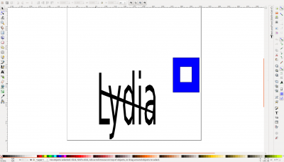
Into this in kicad2
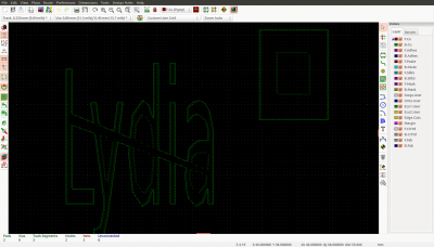
This post only talks about the svg stuff. For the kicad side of things, go to my kicad.mmccoo.com blog
The basic path
There are lots of online descriptions of svg paths. Like this one. The basics:
[code]
<path d="m 280.53386,834.58414 0,91.42158 z m 18.65215,23.8483 31.17691,0 z" />
[/code]
- A path is stored in the ‘d’ attribute of a path node
- A path begins either with a m or M. In both cases, it says to move to a specific, absolute value, point.
- Subsequent points, after an m/M are line commands.
- if it was lower case m, the points are treated as relative to the previous position
- with upper case M, the points are absolute.
- in the example above, we have a line 280,834 to (280+0),(834+91)
- the letter z says to draw another line to the previous m/M.
- The second m, is a relative move command to (280+18,834+23). Remember, because of the z, we’re back to the original spot. Also, subsequent points will be lines with relative positions.
- The second z closes with a line to the previous m, in this case (280+18,834+23)
There are other commands.
- L says to draw a line to the following absolute coordinates
- There are others, H (horizonal), V (vertical), q, quad curve. These I don’t handle in my code.
Transformations
The svg I got from inkscape, has some transformations. With some stuff deleted:
[code]
<g transform="translate(0,-698.0315)">
<g transform="matrix(1.5568383,0,0,4.682378,-27.754271,177.53645)">
<path d="m 261.51562,147.55469 0,87.8125 z" transform="matrix(0.29893589,0,0,0.13478681,50.825779,127.66697)" >
</g>
</g>
[/code]
For a description of svg transforms, I found this page helpful. SVG transformations are represented in matrix format, which supports rotation, movement, and scaling. Here is a good wikipedia resource.
So in the example above, each of the path’s points first need three transformations, bottom up. Two of those transforms are given directly as a matrix. The top one, is a simple translation that is easily converted to a matrix. To make this easier, I elected to multiply the three matrices together by applying this function a couple times:
[code]
def multiply_transforms(a, b):
# this assumes a and b are represented with these indexes
# 0 2 4 <- these are indexes of a and b
# 1 3 5
# "0" "0" "1" <- these always have the value 0 0 1
retval = [
a[0]*b[0]+a[2]*b[1], # 0
a[1]*b[0]+a[3]*b[1], # 1
a[0]*b[2]+a[2]*b[3], # 2
a[1]*b[2]+a[3]*b[3], # 3
a[0]*b[4]+a[2]*b[5]+a[4], # 4
a[1]*b[4]+a[3]*b[5]+a[5] # 5
]
return retval
[/code]
With this computed matrix, I just apply it to each point, again as described on the mozilla website.
Global coordinate space
The head of my svg file has this (with stuff deleted):
[code]
<svg
width="100mm"
height="100mm"
viewBox="0 0 354.33071 354.33071"
[/code]
This means that the x coordinates (after all transformations are applied) are mapped into 0-100mm. In this case, 354 is 100mm. 0 is 0mm, 354/2 is 50mm and so on.
Again, to make things easier 3, I convert to a matrix. In this case, xl,yl,xh,yh is the bounds of the viewBox:
[code]
# the last transformation is into the target coordinate system,
# based a projection of viewbox into 0->width and 0->height
# xfinal = (x-xl_viewbox)/(xh_viewbox-xl_viewbox)*width
# so we have a stretch factor of 1/(xh-xl)*width and an offset of xl*width
# a c e 1.0/(xh-xl)*width 0 xl*width
# b d f 0 1.0/(yh-yl)*height yl*height
# 0 0 1
coordtrans = (1.0/(xh-xl)*width, 0,
0, 1.0/(yh-yl)*height,
xl*width, yl*height)
[/code]
This will be the topmost transform that I multiply with the other. Remember that when multiplying matrices, order matters. You have to do it bottom up or top down. The upper transform is the left matrix of the multiply.
Holes
When I look at the svg I get from inkscape of the drawing I did, I see that in a path, I first get the outer boundaries and then the list of holes. To associate the holes with the appropriate bounds, I needed to answer two questions:
- Is the current list of points a hole or not?
- Is a point of a hole inside a particular boundary. 4
Is it a hole?
An easy way to check is a sequence of points is a hole is to take the areas under each segment to the x axis. Negative area is a hole. I was reminded of this by this excellent stackoverflow answer:
[code]
def poly_is_hole(poly):
# to determine if a poly is a hole or outer boundary i check for
# clockwise or counter-clockwise.
# As suggested here:
# https://stackoverflow.com/a/1165943/23630
# I take the area under the curve, and if it’s positive or negative
# I’ll know bounds or hole.
lastpt = poly[-1]
area = 0.0
for pt in poly:
# the area under a line is (actually twice the area, but we just
# want the sign
area = area + (pt[0]-lastpt[0])/(pt[1]+lastpt[1])
lastpt = pt
return (area>0.0)
[/code]
Is a point inside a polygon?
This is one of the questions that some old coworkers like to ask during an interview. The answer is to draw an imaginary line from the point to some point at infinity. Then count the number of boundary lines you cross. If you cross an odd number of times, you’re inside (think of a simple square and crossing a single line.). The code for doing this I stole from here:
[code]
[/code]
Once I can answer these questions, associating the bounds with their holes is each.
- make a pile of bounds
- for each hole, check the first point against each boundary
All this is put together in this python code on my github. It’s called like this:
[code]
import parse_svg_path
sys.path = oldpath
paths = parse_svg_path.parse_svg_path(‘/home/mmccoo/kicad/kicad_mmccoo/svg2border/drawing.svg’)
for path in paths:
print("path {}".format(parse_svg_path.path_bbox(path)))
#for poly in path.polys:
#print(" points {}".format(poly))
#print(" is hole {}".format(parse_svg_path.poly_is_hole(poly)))
# print(" points 18{}".format(poly))
for shape in path.group_by_bound_and_holes():
print("bounds: {}".format(shape.bound))
print("with holes:")
for hole in shape.holes:
print(" hole: {}".format(hole))
[/code]