In this post, I talk mostly about displaying to graphics devices. One of those devices uses I2C interface, which I haven’t talked about in previous posts, so using I2C is an important topic I cover as well. I2C is a common communications protocol for talking to peripheral devices. Temperature sensors, memories,… anything.
As always, working code can be found in my github. I use the u8g2 library and most of the other code is STMCube generated. The interesting stuff I wrote to put it together is in main.c.
What parts will I be using?
- stm32f103c8t6 board (<$2)
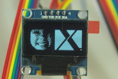
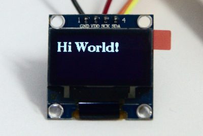
- I2C OLED display based on SSD1306 (~$2.50)
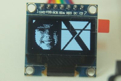
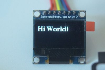
- SPI OLED display ($2.50). If buying on aliexpress, make sure the picture shows 7 pin connections. If you see only 4, it’s the I2C variant. They put SPI in the title, since the underlying hardware supports SPI.
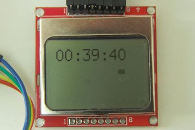
- Nokia 5110 display ($2). Bigger display, not as bright, lower resolution, but still very nice.
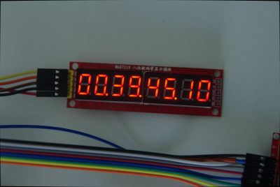
- MAX7219 based 8 digit seven segment display ($1.25)
- A logic analyzer module is helpful for getting things to work (~$5). I used this in my previous post.
I2C Erratta
The biggest gotcha, which I haven’t entirely overcome, is a bug in STM’s i2c hardware. (see section 2.13.7 of the link). There are two steps for solving the problem:
- The I2C clock has to be enabled before GPIOB is enabled. When I do this, things work, more detail below. Over time, I2C can lock up again.
- Do the workaround mentioned in the eratta. It would have been nice if ST had given more than pseudo code. Actual code can be found here.
STMCubeMX
- In I2C1 section, enable to I2C (PB6 and PB7 will become your clk and data pins connecting to the modules SCK and SDA pins respectively)
- In the configuration tab you may want to increase the I2C speed. 1
- Otherwise, the settings are the same as in my previous post.
After clicking on the generate source code button, you’ll want to move these lines (see my github code if this isn’t clear enough)
[code]
/* Peripheral clock enable */
__HAL_RCC_I2C1_CLK_ENABLE();
[/code]
so that it happens before this
[code]
/**I2C1 GPIO Configuration
[/code]
Otherwise, the I2C busy flag will be stuck high and the I2C transmits will not work.
Scanning I2C to see what responds
The code below does a roll call through all I2C addresses to see who’s alive. I2C address space is only 7 bits wide, so only 128 addresses to look at. 2
Since I’m basing this project off of my last post (part 3), UART is still on. That post also talks about how to listen to UART messages on your linux machine.
[code]
// this is basically a I2C address scanner.
// I used it to verify that oled is at 120 and 121.
// the actual addresses are half that and the second is simply the other
// of read/write.
uint8_t ii2messagealive[] = "I2C channel xxx is alive\n";
uint8_t ii2messagedead[] = "I2C channel xxx is dead\n";
for(uint8_t i=0; i<128; i++) {
uint8_t pData[] = "hello";
HAL_StatusTypeDef iicstatus UNUSEDVAR;
iicstatus = HAL_I2C_Master_Transmit(&hi2c1, i, pData, sizeof(pData), 10);
if (iicstatus == HAL_OK) {
byte_at_string(ii2messagealive+12, i);
HAL_UART_Transmit(&huart1, ii2messagealive, sizeof(ii2messagealive), HAL_MAX_DELAY);
} else {
byte_at_string(ii2messagedead+12, i);
HAL_UART_Transmit(&huart1, ii2messagedead, sizeof(ii2messagedead), HAL_MAX_DELAY);
}
}
[/code]
In my case, the OLED display responds to 0x78 or DEC120. According to the SSD1306 datasheet, section 8.1.5, this makes sense 3
So how do you convince the display to display something?
Looking through the datasheet, I can’t really make heads or tails of how to configure this thing and tell it to display stuff. Luckily, someone else has already done this and much more in the U8G2 library.
Setting up U8G2 is actually pretty easy once I figured out a couple things that aren’t in the doc. These are the things I’ll focus on here. You should start with this doc page. In a nutshell, once you have it configured, you can use code like this:
[code]
u8g2_FirstPage(u8g2);
do {
u8g2_SetFont(u8g2, u8g2_font_ncenB14_tr);
u8g2_DrawStr(u8g2, 0,24,"Hi World!");
u8g2_SendBuffer(u8g2);
} while ( u8g2_NextPage(u8g2) );
[/code]
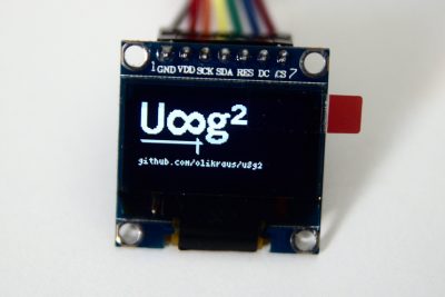
To generate this:
What are the pages that are being looped through? In order to save memory/RAM space, you can tell setup to only save 128 or 256 bytes at a time. This could represent a couple of display lines. So you have to retell u8g2 about your drawing for each set of 128/256 bytes. I’m give more details on displaying stuff later.
Configuring u8g2 to talk to your device
Before you can ask u8g2 to display something, you need to configure/initialize it. From the u8g2 documentation, you need something like below. You can find my actual code on github, (look for u8x8_byte_my_hw_i2c, u8x8_byte_my_hw_spi, and u8x8_gpio_and_delay_mine).
[code]
u8g2_t u8g2; // a structure which will contain all the data for one display
…
u8g2_Setup_ssd1306_i2c_128x64_noname_2(&u8g2, U8G2_R0, u8x8_byte_sw_i2c, u8x8_gpio_and_delay_lpc11u3x); // init u8g2 structure
u8g2_InitDisplay(&u8g2); // send init sequence to the display, display is in sleep mode after this,
u8g2_SetPowerSave(&u8g2, 0); // wake up display
[/code]
My comments on this code:
- I’m using the c api; there’s also a cpp variant. The u8g2 variable is basically a class object.
- The setup function is basically a class constructor. Which constructor you want depends on
- which display you have. SSD1306 is only one of many that are supported.
- I2C vs SPI. The I2C version has I2C in the name, the SPI version omits this 4
- The number that the function name ends with (_2, in this case, right after the noname) controls how much memory/RAM you want to use for graphics. _1 means use 128 bytes for display, _2 means use 256, _f means store all pixels. This is why you have to redraw everything for each “page”.
- The first two arguments are easy, the class object and an enum value telling the library whether display is rotated in your application.
- The last two arguments are function pointers. At First, I was a little confused about what should go into these, but I figured it out with the help of gdb and stlink. They’re easy.
u8x8_gpio_and_delay
I’ll start with the second of the two function pointers. It’s the easiest of the two… because it doesn’t need to do anything. I think this for two reasons:
- My gpios, i2c pins, spi pins… are already initialized. I’m not trying to use any pins in multiple ways. The STMCube code already does this.
- I’m not using software based i2c/spi 5 I tell the hardware modules the bytes I want to send and wait.
Here’s the required function signature from u8x8.h:
[code]
typedef uint8_t (*u8x8_msg_cb)(u8x8_t *u8x8, uint8_t msg, uint8_t arg_int, void *arg_ptr);
[/code]
which means you want a function that looks like this:
[code]
uint8_t u8x8_gpio_and_delay_mine(u8x8_t *u8x8, uint8_t msg, uint8_t arg_int, void *arg_ptr)
[/code]
msg is basically an enum with values like: U8X8_MSG_GPIO_AND_DELAY_INIT, U8X8_MSG_DELAY_NANO, and more U8X8_MSG_DELAY_I2C.
An example of one of these callbacks can be found in the u8g2 source. Again, it doesn’t do anything.
u8x8_msg_cb
This is the more interesting of the two functions you need to supply. Here’s the required function signature, also in u8x8.h. As another example implementation, you might look at the u8x8_byte_4wire_sw_spi function in u8g2.
[code]
typedef uint8_t (*u8x8_msg_cb)(u8x8_t *u8x8, uint8_t msg, uint8_t arg_int, void *arg_ptr);
[/code]
Which translates into a function like this:
[code]
uint8_t
u8x8_byte_my_hw_i2c(
U8X8_UNUSED u8x8_t *u8x8,
U8X8_UNUSED uint8_t msg,
U8X8_UNUSED uint8_t arg_int,
U8X8_UNUSED void *arg_ptr)
[/code]
and again msg is basically an enum 6, telling the function what to do. Initialize the necessary pins, start/end transfer…
Because this first example uses i2c and because this interface may be software implemented, (ie bit swizzling, which mine is not), the messages are broken into: here’s the device address, here’s a byte, here are some more bytes, ok go ahead and send. So my function carries a bit of state from call to call to collect the bytes. My function also has the oled’s i2c address hardcoded 7. So it begins with this buffer of bytes to send:
[code]
#define MAX_LEN 32
static uint8_t vals[MAX_LEN];
static uint8_t length=0;
[/code]
Then messages of interest are:
- U8X8_MSG_BYTE_INIT. My version does nothing. You could use this to turn on your i2c pins.
- U8X8_MSG_BYTE_SET_DC. This is not relevant for I2c but will be important in the SPI version.
- U8X8_MSG_BYTE_START_TRANSFER: ok, it’s about to send the function some bytes. I just set my buffer length/index to 0
- U8X8_MSG_BYTE_SEND: this one gives me bytes. The number of bytes is in the arg_int argument. I just copy the bytes from arg_ptr into vals
[code]
if ((arg_int+length) <= MAX_LEN) {
for(int i=0; i<arg_int; i++) {
vals[length] = args[i];
length++;
}
} else {
uint8_t umsg[] = "MSG_BYTE_SEND arg too long xxx\n";
byte_at_string(umsg+27, arg_int);
sendUARTmsgPoll(umsg, sizeof(umsg));
}
[/code]
- U8X8_MSG_BYTE_END_TRANSFER. Now it’s time to actually send the data.
[code]
while(HAL_I2C_GetState (&hi2c1) != HAL_I2C_STATE_READY) { /* empty */ }
const uint8_t addr = 0x78;
HAL_I2C_Master_Transmit(&hi2c1, addr, vals, length, 10);
[/code]
I’m only including the interesting code here. For the full implementation, see my github. Look for the function named u8x8_byte_my_hw_i2c.
So what are the things you can display?
The basic template for display with u8g2 is:
[code]
u8g2_ClearBuffer(&u8g2);
u8g2_FirstPage(&u8g2);
do {
// what you want to draw.
// NextPage calls SendBuffer
// u8g2_SendBuffer(&u8g2);
} while ( u8g2_NextPage(&u8g2) );
[/code]
Now we need to populate the “what you want to draw” part.
hello world
[code]
u8g2_SetFont(u8g2, u8g2_font_ncenB14_tr);
u8g2_DrawStr(u8g2, 0,24,"Hi World!");
[/code]
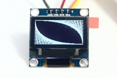
Lines
There are a bunch of graphics primitives. Here’s an example I lifted from jandelgado’s github. It also has a good tutorial that I found helpful.
[code]
int steps = 16;
int dx = 128/steps;
int dy = 64/steps;
int y = 0;
for(int x=0; x<128; x+=dx) {
u8g2_DrawLine(&u8g2, x, 0, 127, y);
u8g2_DrawLine(&u8g2, 127-x, 63, 0, 63-y);
y+=dy;
}
[/code]
U8g2’s logo
u8g2’s own demo code.
[code]
u8g2_SetDrawColor(u8g2, 1);
u8g2_SetFontMode(u8g2, 1); // Transparent
u8g2_SetFontDirection(u8g2, 0);
u8g2_SetFont(u8g2, u8g2_font_inb24_mf);
u8g2_DrawStr(u8g2, 0, 30, "U");
u8g2_SetFontDirection(u8g2, 1);
u8g2_SetFont(u8g2, u8g2_font_inb30_mn);
u8g2_DrawStr(u8g2, 21,8,"8");
u8g2_SetFontDirection(u8g2, 0);
u8g2_SetFont(u8g2, u8g2_font_inb24_mf);
u8g2_DrawStr(u8g2, 51,30,"g");
u8g2_DrawStr(u8g2, 67,30,"\xb2");
u8g2_DrawHLine(u8g2, 2, 35, 47);
u8g2_DrawHLine(u8g2, 3, 36, 47);
u8g2_DrawVLine(u8g2, 45, 32, 12);
u8g2_DrawVLine(u8g2, 46, 33, 12);
u8g2_SetFont(u8g2, u8g2_font_4x6_tr);
u8g2_DrawStr(u8g2, 1,54,"github.com/olikraus/u8g2");
[/code]
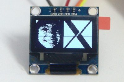
your own bitmaps
One feature that I think is especially cool is the ability to display bitmaps. Say you have an jpg file, you can use ImageMagick’s convert command.
In my case, I used this:
[code]
convert lydia.jpg -crop 64×64 -monochrome -negate lydia.xbm
[/code]
Which gives you something like this to include in your code:
[code]
#define lydia_width 64
#define lydia_height 64
static unsigned char lydia_bits[] = {
0xE0, 0xFF, 0xFF, 0xFF, 0xFF, 0xFF, 0xFF, 0xFF, 0xF0, 0xFF, 0xFF, 0xFF,
0xFF, 0xFF, 0xDF, 0xFF, 0xF0, 0xFF, 0xFF, 0xFF, 0xFF, 0xFF, 0xFF, 0xFF,
… stuff deleted
[/code]
Displaying it is easy:
[code]
u8g2_SetDrawColor(&u8g2, 0);
u8g2_DrawXBM(&u8g2, 0, 0, lydia_width, lydia_height, lydia_bits);
u8g2_DrawXBM(&u8g2, 64, 0, xlogo64_width, xlogo64_height, xlogo64_bits);
[/code]
non-i2c stuff
Since this post is largely about using the u8g2 library and display in general, I’m also including two more sections.
- how to talk to SPI modules via u8g2
- how to talk to the max7219 based display module.
SPI based display
One of the nice things about I2C is that you can have a bunch of devices all communicating on the same two wires. (SCK and SDA) SPI doesn’t have addressing built into the protocol, so additional pins need to be involved. In the case of the SPI display, total pin count goes to 5 8. The three additional pins are:
- D/C# – data (on high)/command(on low). This tells the display whether you’re sending data or a command. This is not part of common SPI (as I’ve experienced it).
- CS#/SS# – chip select/slave select, active low. The other SPI pins can be shared between multiple devices. This the signal that tells a specific device, “hey, I’m talking to you”
- Reset# – active low. In a way, this pin should just be tied high. The problem I’ve experienced is during debug. When invoking openocd/gdb/pressing reset, the oled display is not powered down. The configuration sequence doesn’t work for me unless the module is in full reset state. So I pulse it low in the beginning of my main function.
Hardware interface callback
Just like with I2C, u8g2 expects a callback function pointer. It’s very similar but also rather different.
- Instead of queuing up a bunch of bytes to send, we can just send them
- Set/reset DC
- Set/reset CS
This function works for both the OLED SPI display and the nokia 5110. You just need to add a flag to flip the correct CS line. You have to use the appropriate u8g2 setup function (u8g2_Setup_ssd1306_128x64_noname_f and u8g2_Setup_pcd8544_84x48_f for SPI OLED and Nokia 5110 respectively)
[code]
case U8X8_MSG_BYTE_SEND: {
while(HAL_SPI_GetState (&hspi1) != HAL_SPI_STATE_READY) { /* empty */ }
HAL_SPI_Transmit (&hspi1, arg_ptr, arg_int, HAL_MAX_DELAY);
amountsent+= arg_int;
[/code]
Need to set/reset the DC pin:
[code]
case U8X8_MSG_BYTE_SET_DC: {
if (arg_int) {
GPIOA->BSRR = GPIO_BSRR_BS4;
} else {
GPIOA->BSRR = GPIO_BSRR_BR4;
}
[/code]
Set/reset CS/SS
[code]
case U8X8_MSG_BYTE_START_TRANSFER:
CSPORT->BSRR = CSRESET;
break;
case U8X8_MSG_BYTE_END_TRANSFER:
CSPORT->BSRR = CSSET;
break;
[/code]
MAX7219 8 digit, seven segment display
Sometimes, you don’t need a fancy schmancy display. You just need some numbers. For 1.25, you can. It’s also easy to cascade a bunch of these in serias, though I don’t talk about that here. Note the header pads on the right for this purpose.
For this module, I don’t use a library 9. I just send the needed config messages myself based on the datasheet.
If you look at the code on my github, you’ll find the functions seven_segment_init and seven_segment_display. They have cut/paste text from the relevant parts of the datasheet. I’ll summarize here nonetheless.
There are two modes for the MAX7219 chip, decode mode and non-decode mode. Seven segment displays are mostly there to display numbers. The chip makes this easy by translating (decoding) a 0-9 value into lighting the relevant LEDs. Do you really want to think about whether the top left LED should be lit up for the number 0? If you don’t use decode mode. If you do want to control LEDs individually, you use non-decode mode. 10
Init
There are only a handful of things you have to set to configure this device:
- For which digits do you want decode mode.
- How bright should the LEDs be? This affects the duty cycle.11
- If you are not using all 7 digits, you can tell it to skip some of them via the scan limit setting
- display test is not something I’ve played with. you usually want it set to off
- shutdown needs to be turned to 0x1, “normal operation” 12
That’s all you need to configure. I’m not including further how to details because I think the code (function seven_segment_init) explains it well.
Displaying some numbers
Assuming you’re in decode mode, you just send one of the eight DIGIT commands (DIGIT_0 through DIGIT_7) with the number you want displayed. If you want a decimal point, set the highest bit of the value you want. (IE value | (1<<7)). There’s really not much more for me to explain.
So, there’s a bunch of ways to display graphics. The u8g2 library makes most of this really easy and powerful. I’ve found SPI to be easier to deal with than I2C (even with the extra pins), but there are some devices that are only I2C. Speaking I2C is not that hard once you overcome the STM32 bug.
In my application, I want a fast display refresh rate. 200kb is still slower than SPI. Graphics can require some bits. ↩
actually only 112, but I look at them all anyway. The difference doesn’t really matter since the correct address is set by the manufacturer of the part you’re talking to. (+/- a bit or two of configuration)↩
I find the datasheet confusing. I sort of understand what it says, given that I already knew my display responded to 120, but if you asked me to guess the address based on the datasheet,… I’d probably get it wrong.↩
for clarity, I think spi should be in the name. I’m not gonna complain, the library’s very nice.↩
I think this is why this function is needed, but I don’t know for sure. ↩
I wonder why it’s not an enum instead of the #defines that are used.↩
the ssd1306 is theoretically configurable to use multiple address, but I haven’t tried↩
I’m not including vcc/gnd in the counts↩
I believe the u8g2 library can talk to the underlying MAX7219 chip to do led arrays ↩
for example, when you’re using the chip to turn on led arrays↩
This makes it tricky to do an LED array with different brightness across the array. I think I’ve seen that done with this chip, but perhaps I’m misremembering. ↩
seems reversed to me. ↩